Button Grid PCB
ESP32-S3 controller for an 8×8 diode button matrix with 64 individually switched 12 V LEDs (8× 74HC595 + 8× ULN2803A). Two-layer board, 208 × 110 mm, built for JLCPCB.
Board
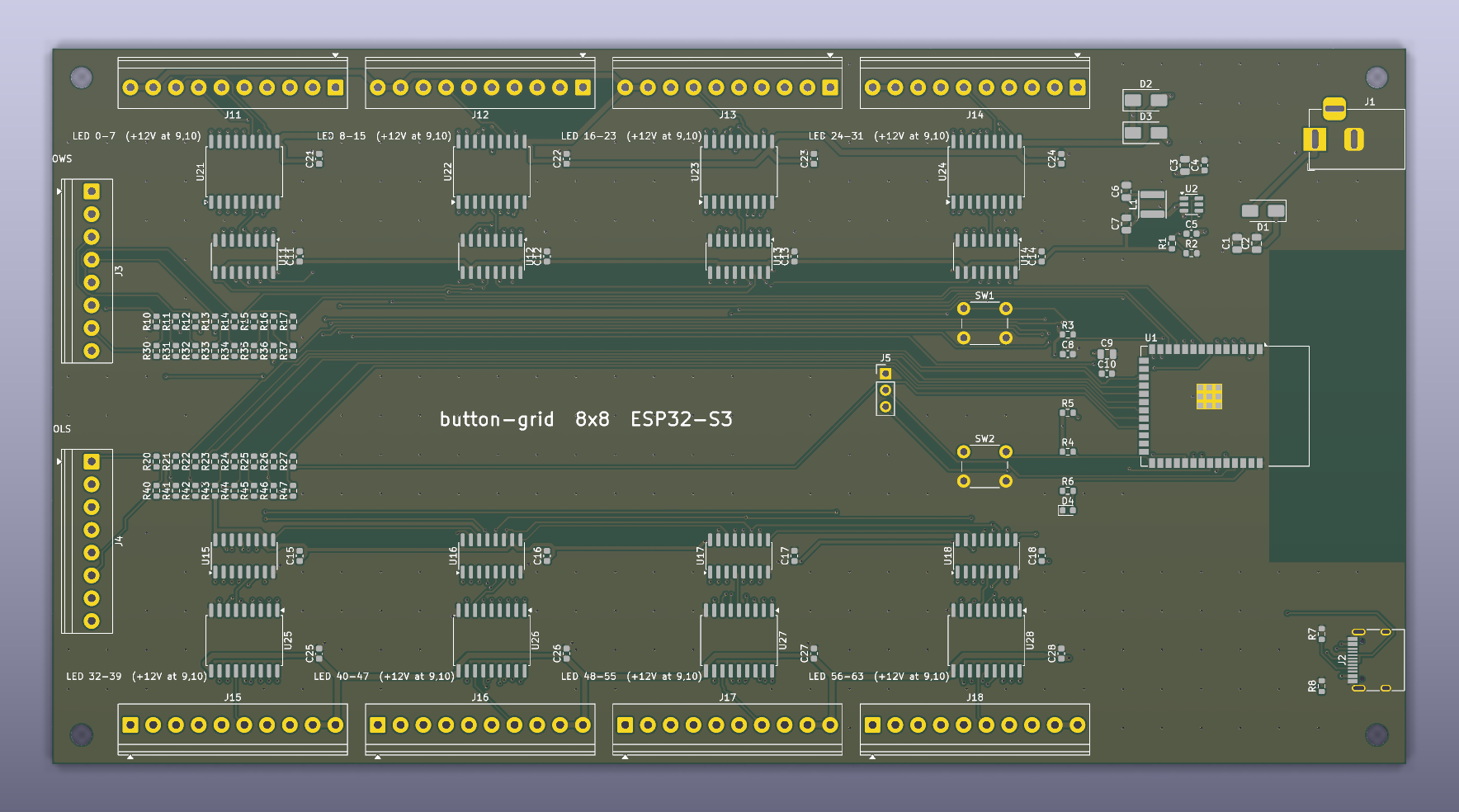
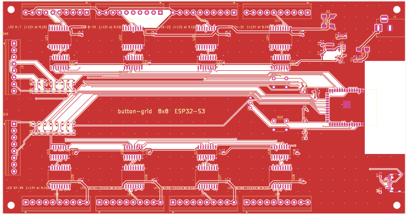
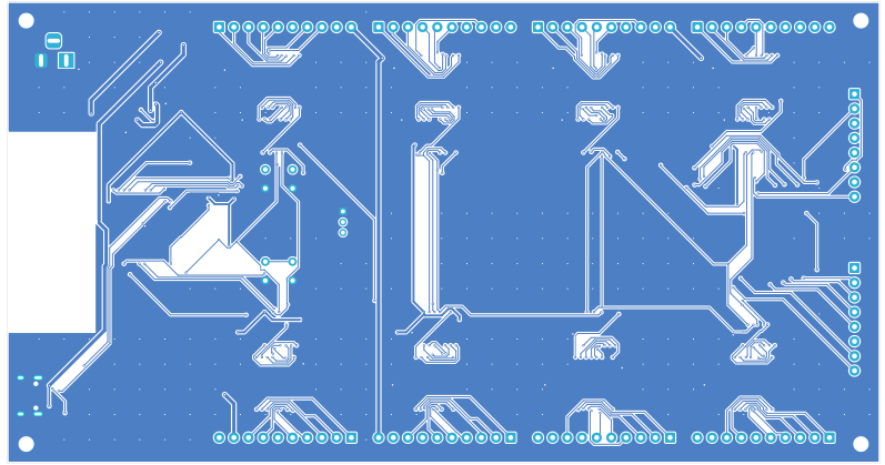
How it works
- LEDs: 74HC595 chain (bank 1 first) → ULN2803A low-side switches → screw terminals.
Each 10-pole terminal: pins 1–8 = LED cathode wires, pins 9–10 = +12 V for the LED anodes.
LEDs are dark at power-up (
OEis pulled high until firmware enables it). - Buttons: rows and columns go straight to 16 ESP32 GPIOs through 100 Ω resistors with 22 kΩ pull-ups (terminals ROWS and COLS on the left edge).
- Power: 12 V wall adapter (5.5×2.1 mm, centre +, ≥2 A) → SS54 reverse-polarity diode → LED supply; TPS54202 buck → 3.3 V logic. USB-C alone can also power the logic for flashing.
Design files
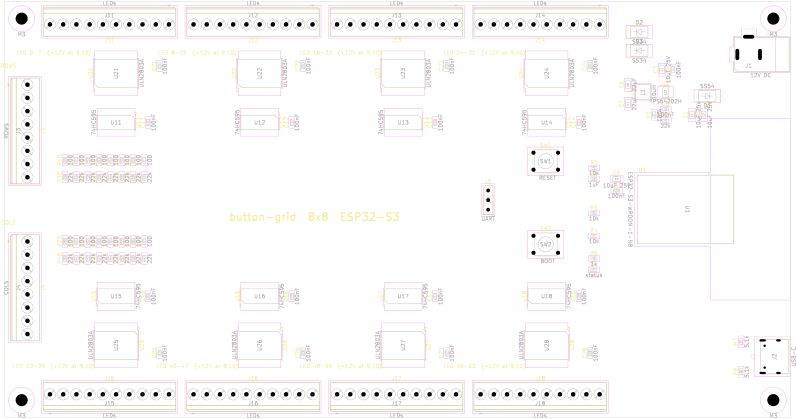
Interactive viewer (pan/zoom, click parts). Use the panel to switch between the root schematic, the LED-bank sheet and the PCB. Open the files themselves in KiCad 9.
- KiCad project (.zip)schematic + PCB, open in KiCad 9
- Schematic PDFall sheets
- Assembly drawing (SVG)part placement and references
Tests
Run automatically on every push by GitHub Actions (hardware/scripts/check.sh).
Electrical rules check (ERC)
KiCad checks the schematic for unconnected pins, undriven power inputs, conflicting outputs, dangling labels and similar mistakes.
Full report
ERC report (2026-10-14T21:41:10+0000, Encoding UTF8)
Report includes: Errors, Warnings, Exclusions

***** Sheet /

***** Sheet /Bank 1/

***** Sheet /Bank 2/

***** Sheet /Bank 3/

***** Sheet /Bank 4/

***** Sheet /Bank 5/

***** Sheet /Bank 6/

***** Sheet /Bank 7/

***** Sheet /Bank 8/

 ** ERC messages: 0  Errors 0  Warnings 0
Connectivity assertions
Our own script (hardware/scripts/check_netlist.py) reads the netlist and checks the intended circuit pin by pin: all 64 LED terminals go through a ULN2803 output to the right 74HC595 output; the shift registers form one chain from ESP32 IO38 to IO42; clock/latch/enable reach every chip; every matrix line has its series resistor and pull-up; USB CC resistors; buck converter feedback gives 3.3 V; no strapping pins used; every assembled part has an LCSC number.
Full report
buck output voltage: 3.305 V
108 components, 204 nets, 64 LED channels checked
netlist OK
Design rules check (DRC) + schematic parity
KiCad checks the PCB against JLCPCB-safe manufacturing limits (clearances, track widths, drill sizes, board edge), that every net is fully routed, and that the PCB matches the schematic exactly.
Full report
** Drc report for button-grid.kicad_pcb **
** Created on 2026-10-14T21:41:13+0000 **
** Report includes: Errors, Warnings, Exclusions **

** Found 1 DRC violations **
[silk_over_copper]: Silkscreen clipped by solder mask
    Local override; warning
    @(223.3200 mm, 70.0000 mm): Reference field of C2

** Found 0 unconnected pads **

** Found 0 Footprint errors **

** End of Report **
Order at JLCPCB
- Gerber + drill files (.zip)upload on jlcpcb.com → Add gerber file
- BOM (CSV)PCB Assembly → BOM file
- Pick & place / CPL (CSV)PCB Assembly → CPL file
- Hand-solder parts list (CSV)screw terminals, barrel jack, buttons, header
- Upload the gerber zip. Defaults are fine: 2 layers, 1.6 mm, HASL. Quantity 5.
- Enable PCB Assembly, "Economic", top side, assemble 2 boards.
- Upload the BOM and CPL. Check that every line matched a part and is in stock.
- On the placement preview, check the rotation of the chips (pin-1 dot) and the USB-C connector, and fix it with the rotate button if one is turned.
- Order the through-hole parts from the hand-solder list (LCSC/Amazon/eBay) and solder them yourself: 3.5 mm pitch screw terminals (8× 10-pole, 2× 8-pole), 5.5×2.1 mm barrel jack, 2× 6 mm push buttons, 1×3 pin header.
Parts assembled by JLCPCB
| Comment | Designator | Footprint | LCSC Part # |
|---|---|---|---|
| 10uF 25V | C1,C2,C3,C9 | C_0805_2012Metric | C15850 |
| 100nF | C4,C5,C10,C11,C12,C13,C14,C15,C16,C17,C18,C21,C22,C23,C24,C25,C26,C27,C28 | C_0603_1608Metric | C14663 |
| 22uF | C6,C7 | C_0805_2012Metric | C45783 |
| 1uF | C8 | C_0603_1608Metric | C15849 |
| SS54 | D1 | D_SMA | C22452 |
| SS34 | D2,D3 | D_SMA | C8678 |
| status | D4 | LED_0603_1608Metric | C2286 |
| USB-C | J2 | USB_C_Receptacle_HRO_TYPE-C-31-M-12 | C165948 |
| 10uH | L1 | L_Sunlord_SWPA4030S | C38117 |
| 100k | R1 | R_0603_1608Metric | C25803 |
| 22k | R2,R30,R31,R32,R33,R34,R35,R36,R37,R40,R41,R42,R43,R44,R45,R46,R47 | R_0603_1608Metric | C31850 |
| 10k | R3,R4,R5 | R_0603_1608Metric | C25804 |
| 1k | R6 | R_0603_1608Metric | C21190 |
| 5.1k | R7,R8 | R_0603_1608Metric | C23186 |
| 100 | R10,R11,R12,R13,R14,R15,R16,R17,R20,R21,R22,R23,R24,R25,R26,R27 | R_0603_1608Metric | C22775 |
| ESP32-S3-WROOM-1-N8 | U1 | ESP32-S3-WROOM-1 | C2913198 |
| TPS54202H | U2 | TSOT-23-6 | C527684 |
| 74HC595 | U11,U12,U13,U14,U15,U16,U17,U18 | SOIC-16_3.9x9.9mm_P1.27mm | C5947 |
| ULN2803A | U21,U22,U23,U24,U25,U26,U27,U28 | SOIC-18W_7.5x11.6mm_P1.27mm | C9683 |
Parts you solder yourself
| Qty | Value | Designators | Footprint | LCSC (optional) |
|---|---|---|---|---|
| 1 | 12V DC | J1 | BarrelJack_Horizontal | C381116 |
| 1 | ROWS | J3 | TerminalBlock_Phoenix_PT-1,5-8-3.5-H_1x08_P3.50mm_Horizontal | |
| 1 | COLS | J4 | TerminalBlock_Phoenix_PT-1,5-8-3.5-H_1x08_P3.50mm_Horizontal | |
| 1 | UART | J5 | PinHeader_1x03_P2.54mm_Vertical | |
| 8 | LEDs | J11,J12,J13,J14,J15,J16,J17,J18 | TerminalBlock_Phoenix_PT-1,5-10-3.5-H_1x10_P3.50mm_Horizontal | |
| 1 | RESET | SW1 | SW_PUSH_6mm | |
| 1 | BOOT | SW2 | SW_PUSH_6mm |